
Building an Assembly
Overview
An assembly in Workday Studio is a graphical assemblage of components that defines the logic of an integration system. Components provide different types of functionality, e.g., transportation, routing, transformation, and error handling. Individual components are connected ("wired") together to form processing chains, the flow of an integration.
Objectives
By the end of this chapter, you will be able to:
- Identify assembly components.
- Create a new assembly project.
- Deploy and launch integrations.
- Review messages in the log file and integration event.
Workday Studio Development Phases
Workday Studio provides an Integrated Development Environment (IDE) that helps developers design and build integrations. It is built on top of the open-source Eclipse™ IDE. With this development tool, you create an assembly from a selection of reusable components that include transport, routing, configuration, and mediation steps. These assemblies form the basis of your integration.
Depending on the integration phase, you use either Workday Studio or the Workday application to work with the integration. Workday Studio integrations have the following distinct phases:
- Design: Using the Workday Studio design-time environment, you develop the assemblies that form your integration.
- Deploy: From Workday Studio, you connect to the Cloud Repository and deploy your integration.
- Configure: Within the Workday application, you configure certain aspects of your integration, including services and notifications.
- Launch: You launch the integration in one of several ways, using either Workday Studio or the Workday application.
- Monitor: After launching, you can track the progress of the integration from Workday Studio or the Workday application. You can also view a consolidated report of the integration process after it has completed.
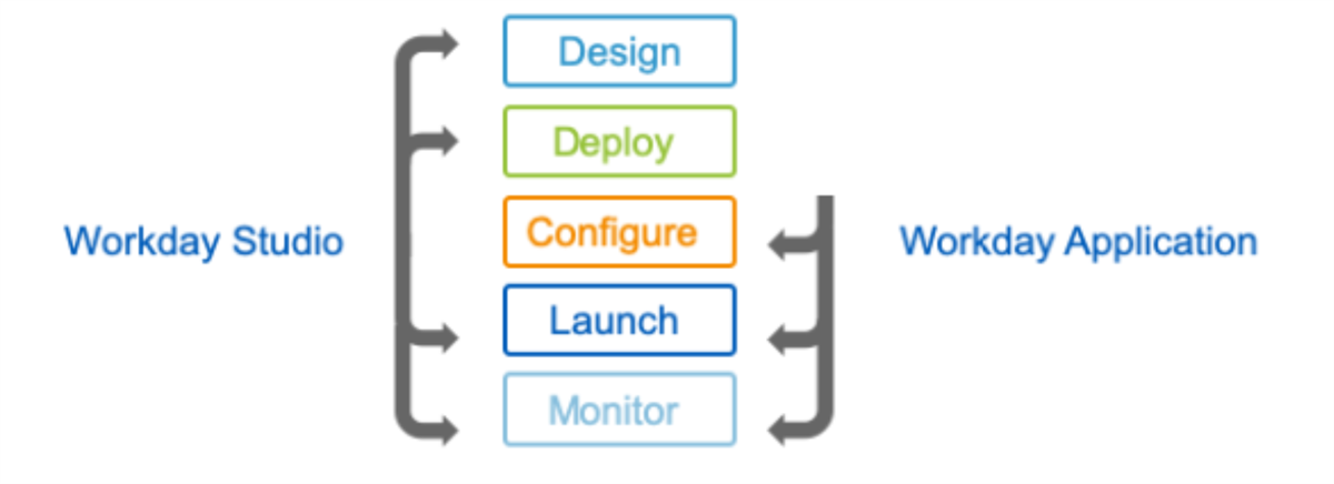
Integration phases
Workday Studio Security Basics
Workday has separate security requirements to set up and launch integration systems based on the integration type. The following security domains grant permissions related to Workday Studio integrations.
Task | Required Domain Access |
|---|---|
Deploy a Workday Studio integration | Integration Build |
Configure one or more integration services | Integration Configure |
Debug a Workday Studio integration | Integration Debug |
Launch or schedule an integration | Integration Event |
View resulting integration events, including integration output documents | Integration Event |
View integration reports, including reports for integration events, exception audits, messages, and integration IDs | Integration Reports |
View and edit an integration's subscriptions | Integration Subscriptions |
Resource
: Refer to the Security for Integrations topic in the Authentication and Security administration guide for information on configuring integration security domains, including for Workday Studio.Assemblies
Assemblies provide a unified diagram for all the core functions of a Workday integration system (transportation, routing, transformation, and error handling). Workday Studio provides this functionality in the form of individual components that are connected (or wired) together to form processing chains.
You design assemblies using the Workday Studio visual assembly editor. This is a graphical editor that allows you to define a flow of messages exchanged between Workday and other systems. The assembly editor provides an extensive range of packaged components for manipulating messages and communicating with other systems over various protocols such as FTP, SFTP, SMTP (email), HTTP, and HTTPS. The assembly editor also supports message construction using the powerful write step, and transformation using XSLT (Extensible Stylesheet Language Transformations) and other built-in data conversion options.
Workday Studio is designed specifically to facilitate building and maintaining integrations with Workday. The purpose-built Workday transports, combined with the Workday public application programming interface (API), remove much of the effort normally associated with system integrations.
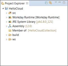
To open the assembly diagram, expand the project in the Project Explorer, and then double-click Assembly.
Project explorer
Assembly Diagram
The assembly diagram consists of components and connections. Components are "wired" together with connections that drive the message flow through the assembly.
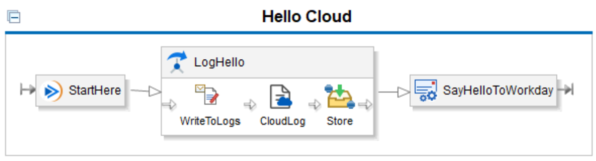
Assembly Diagram
Assembly components are classified into the following categories:
Transports
: The Assembly runtime supports several transports. There are two IN-TRANSPORT components: Workday (workday-in) and local (local-in). In-transport components receive messages from a Workday or local resource. There are multiple OUT-TRANSPORT components that can send messages to a resource (e.g., HTTP, FTP, email, custom) Transports can operate in request-only, or request-response modes.Basic Mediation Components
: Mediations are the main mechanism for modifying and transforming a message as it flows through an assembly. A mediation defines a sequential ordering of one or more individual processing steps that perform operations on a message as it is passed from one step to another within the mediation definition.Mediations can either be synchronous or asynchronous. Synchronous mediations consist of two sub elements, one for request steps and one for response steps. Asynchronous mediations define a single set of steps.
Advanced Assembly Components
: Basic components provide a way to connect processing steps together into processing chains. The advanced components provide a way to dynamically control how the assembly runtime traverses the processing chain.Advanced Mediation Components include:
- Route
- Splitter
- Aggregator
Common Components
: Pre-packaged sub-assembly components delivered by Workday that you can use when developing Workday integrations.These components perform integration tasks that are routinely required by developers.Mediation Steps
: Pre-configured steps that support operations such as transformation, validation, logging, identity, among others. You can also write custom steps using Spring beans.Assembly Design
Using the assembly editor you can graphically build up your assembly by adding and linking transports, mediations, and steps together to define your integration.
There are two representations of an assembly. The first is a graphical representation of the underlying assembly.xml file. This is displayed in the default Design tab. A Source tab also exists and displays the actual Assembly XML. You should add and configure assembly components using the editor, and not by directly modifying component XML within the Source tab.
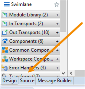
Source tab - XML assembly
The main area of the assembly editor is a graphical representation of the transports, mediations, steps, and general assembly components. These combine to define the overall business processing performed by the assembly. The Palette lists all the assembly components. You can add components to the assembly diagram by dragging them over from the Palette. You can select an element in the diagram to view and edit its properties in the Properties view.
Assembly Palette
The palette, which is located on the left-hand side of the main editor view within the workspace, displays tools for adding assembly components. Add components to the assembly diagram by dragging them from the palette. Hover over an icon to get more information in a tooltip.
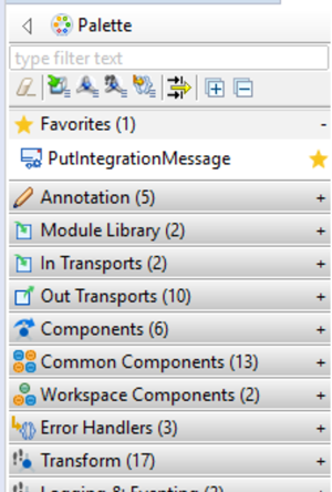
Assembly Tools Palette
The Palette groups components into a number of categories:
- Transports, both in and out
- Components, such as asynchronous and synchronous mediations, routes, aggregators, splitters, common components, and workspace components.
- Mediation steps that transform, manipulate, or log messages.
- Error Handlers
To change the view of the icons on the palette, right-click the palette and select the layout you prefer.
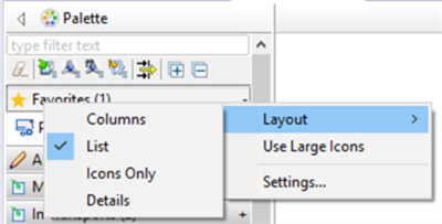
Palette layout
Select a component as a favorite by selecting the star next to it. It will be displayed in the Favorites category.
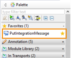
Identified favorite components
Component Properties
Every component has a set of configurable properties. Properties are displayed as a view in the Workday default perspective. Right-click on a component and select the Show Properties View.
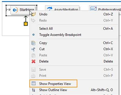
Show Properties View
Select an element in the diagram to view and edit its properties in the properties view.
Properties view
Some components have more than one item with properties. For example, the async mediation component has properties but it also contains components. The log step is located inside of the mediation and has its own set of properties.
In-Transport Components
In-transport components define the starting point of the assembly processing. An assembly must have at least one workday-in transport. If it has more than one, it supports multiple ways to kick off processing.
The assembly runtime also provides the local-in transport, which defines a reusable assembly chain that other assembly chains can call, also known as a subassembly. This is similar to declaring a subroutine in a programming language. A local-out transport is the mechanism by which you can invoke a local-in and is similar to a subroutine call.
Out-Transport Components
Out-transport components take the contents of the message in the mediation context and send it to another system (e.g., an SFTP server). The assembly runtime provides several out-transport components to handle various protocols (e.g., HTTP/S, SFTP, FTP/S, email, and XMPP). If the out-transport is synchronous, it will write the response it receives from the other system back to the mediation message. The assembly runtime provides two workday-out transports:
- workday-out-soapfor sending SOAP messages to your Workday tenant.
- workday-out-restfor retrieving custom reports via Reports-as-a-Service (RaaS).
Workday-In Transport
Every integration's assembly starts with a workday-in transport component that represents the integration system in Workday. The workday-in transport defines the name of the integration system, its launch parameters, and any configurable services.
The assemblies you create in Workday Studio always contain one or more workday-in transports. The workday-in transport is designed specifically to facilitate and expedite integration with the Workday runtime environment. There is a one-to-one relationship between integration systems and workday-ins.
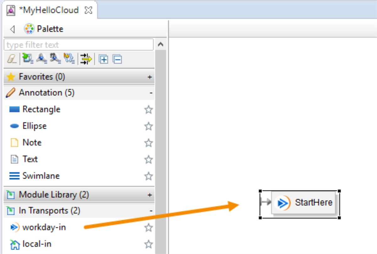
Assembly workday-in transport component
Workday-In Transport Properties
When you select the workday-in transport, the component properties display in the Properties view, below the assembly.
Tab | Function |
|---|---|
Common | Allows you to configure the component's ID and routing details. |
Advanced | Allows you to set the integration system name in Workday. |
Launch Parameters | Allows for configuration of launch parameters. |
Service | Allows for defining integration services such as the Attribute and Map Service, Sequence Generators, Report Service, and Listener Service. |
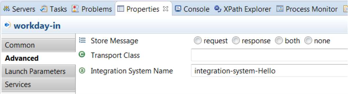
Workday-in transport properties
Components
Basic Mediation Components
Basic mediation components are the main mechanism for modifying and transforming a message as it flows through an assembly. A mediation defines a sequential ordering of one or more individual processing steps. These processing steps perform operations on a message as it is passed from one step to another within the mediation definition.
Mediations can either be synchronous or asynchronous. Synchronous mediations consist of two sub elements, one for request steps and one for response steps. Asynchronous mediations define a single set of steps.
Synchronous vs. Asynchronous Mediation Components
Every time a Workday Studio-built integration is launched, it follows two phases of processing:
- Push or Request Phase:Components are executed in order (according to connections) and are added to a stack.
- Pop or Response Phase:Once the push phase is complete, components are removed from the stack last-in-first-out, until the entry point is reached (workday-in or local-in).
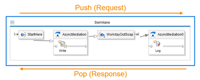
Push (Request) and Pop (Response) Phases
- Async-Mediations have only one lane, a placeholder for steps that execute during the push (request) phase.
- Sync-Mediations have two lanes, a placeholder for steps that execute during the push (request) phase and a separate placeholder for steps that execute on the pop (response) phase.
The following diagram shows two distinct design patterns which produce the same result. In the top assembly, the Log_request_success step gets processed during the push (request) phase after the WorkdayOutSoap and there are no processing instructions in the pop (response) phase. In contrast, the bottom assembly has no processing instructions after the WorkdayOutSoap in the push (request) phase which means the pop (response) phase begins and the bottom lane of the SyncMediation, Log_request_success, is processed.
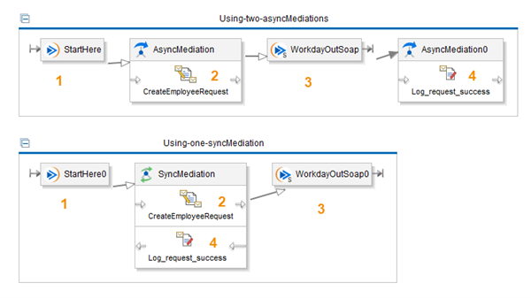
async-mediations vs sync-mediations
There are two types of connectors on an assembly diagram:
- Request Connectors:Represent the connection between components on the push (request) phase except for connections originating from an out-transport. They can be identified by a hollow or white arrowhead.
- Response Connectors:Represent the connection from an out-transport (since the assembly receives its response) or the routing applicable after executing the response steps in a synchronous mediation component. They can be identified by a solid or black arrowhead.
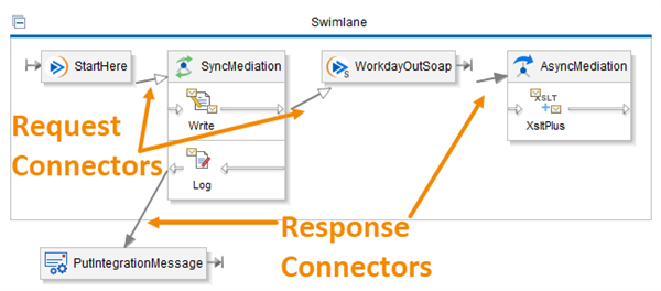
Workday Studio Assembly Diagram Connectors
Advanced Mediation Components
Basic components provide a way to connect processing steps together into processing chains. The advanced components provide a way to dynamically control how the assembly runtime traverses the processing chain.
Advanced Mediation Components include:
- Route
- Splitter
- Aggregator
Route Component
The Route component enables dynamic control over the integration's flow, allowing you to conditionally route messages based on specific criteria
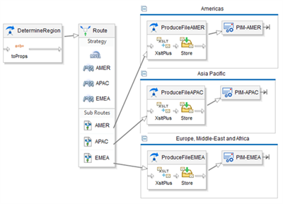
Route component
The assembly runtime provides several strategies to choose from.
Some route strategies have built-in logic to determine the sub-route taken:
- round-robin: alternates between sub-routes each time the route executes.
- failover:allows the assembly processor to try a sub-route, then a different sub-route, if it encounters an error.
- all:allows every sub-route to execute in turn.
Other strategies allow you to write expressions to determine the sub-route taken:
- xpath: selects a sub-route on the basis of an XPath expression.
- mvel: selects a sub-route on the basis of an MVEL expression.
- regex: selects a sub-route on the basis of a regular expression.
Finally, there are strategies that provide unique functionality:
- loop:allows MVEL expressions to set properties in the MediationContext to enable iteration.
- doc-iterator:iterates through integration attachments (typically retrieved files) and copies their contents into a MediationContext variable.
Scalability
Assemblies provide a number of features to enable the creation of scalable integrations. All integrations must be developed in a scalable way and must assume that the data extract they process can be arbitrarily large. Whenever you process employee information for example you must assume that the number of employees can change over time. Workday Studio provides different approaches to process data extracts in a scalable manner:
- Splitter and Aggregator (found in the Palette under Advanced Components)
- Streaming (XSLT 3.0)
Splitter Component
The splitter is a mediation component that can process bulk messages which contain more than one data record. It allows you to define a processing path to be performed on each individual record as it iterates through the records in the bulk message. This component is similar to the route component, in that it requires a strategy.
You add strategies to the splitter component by selecting the appropriate icon from the context toolbar when you hover over the splitter component.
The various splitter strategies include:
- Custom-splitter
- Json-splitter
- Standard-splitter
- Unzip-splitter
- Xml-stream-splitter
- Xpath-splitter
- Mtable-splitter
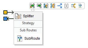
Aggregator Component
The aggregator component's primary function is to concatenate individual messages into a single batch message, which is then routed to the configured destination. While it can be used with a splitter to rebuild bulk messages, the aggregator offers a powerful and efficient way to combine messages from various sources
Configurable options include:
- Force Batch When
- Collate When
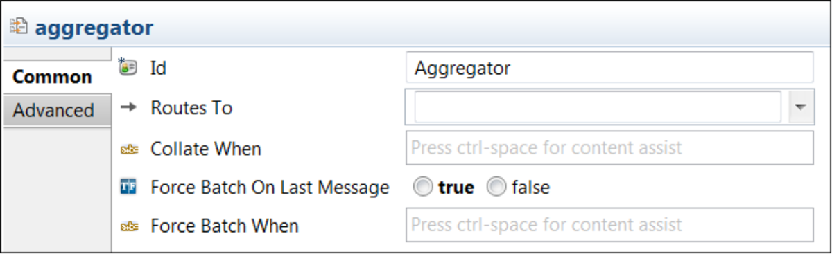
Aggregator properties
Each aggregator requires a batch strategy and a collater. The batch strategy determines when the aggregator should batch records it has been collecting into a bulk message and can be based on size (number or records) or time. A collater provides properties that control the characteristics of the bulk message created upon batching.
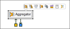
Aggregator component
Common Components
Workday Studio provides several sub-assembly components that you can use when developing Workday integrations. Workday Studio displays sub-assembly components on the Common Components tab of the assembly editor palette. When you add a sub-assembly from the common components category to the assembly diagram, Workday Studio inserts a local-out element in the assembly XML source with the appropriate endpoint for the sub-assembly in the Workday runtime. An example of a common component is PutIntegrationMessage, which sets a message in the integration event and also allows for some output document manipulation.
Wiring Components
When a message arrives into an assembly at an in-transport, the path it takes through the assembly is defined by connectors between transports and message-consuming components such as mediations and routers. The message output from each component becomes the input to the component it is connected to.
Components are connected to one another using connection handles. The routes-to and routes-response-to connectors are different colors, making it easy to distinguish them. Connect components by hovering over a source component until the connection handles display, then dragging one over to the target component.
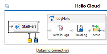
Define a message path
In addition to drag and drop, you can connect a component to another component by selecting the target component from the Routes To drop-down list.
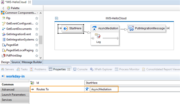
Routes To property on Common tab
Deploy to Workday
Once the assembly is complete and saved, you deploy it to Workday. Right-click the project in the Project Explorer and select Deploy to Workday.
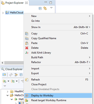
Deploy to Workday menu item
Next you need to select an environment and ensure that you select the check box with the label Include source code in deployed CLAR.
Once you deploy your integration, you can view it in the Cloud Explorer
.
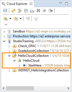
Cloud Explorer Structure
You can also view it in Workday. Search for View Integration System and select your integration.
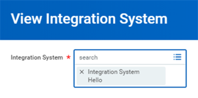
View Integration System task
Launching an Integration in Workday Studio
You can launch an integration system from the Workday Studio Cloud Explorer. Select the connection (e.g., StudioTraining), and expand the collection and the project until you reach a workday-in transport (e.g., StartHere). Right-click and select Launch Integration.
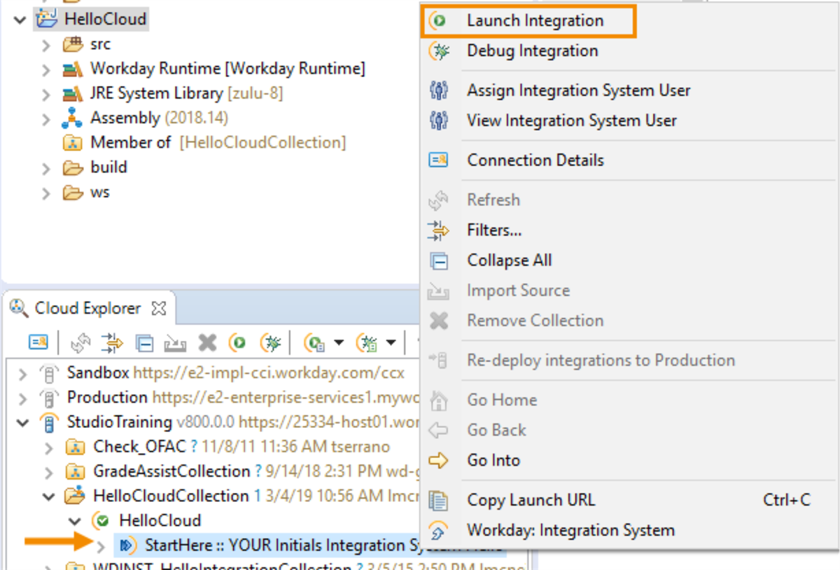
Launch integration menu item
Review the Launch Integration dialog box and select Launch.
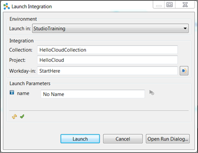
Launch Integration wizard
The first time you launch an integration system, the Launch Parameters are displayed. When you launch that same integration system from Workday Studio again, the launch parameters are not displayed. To view and change launch parameters, select the Open Run Dialog button.
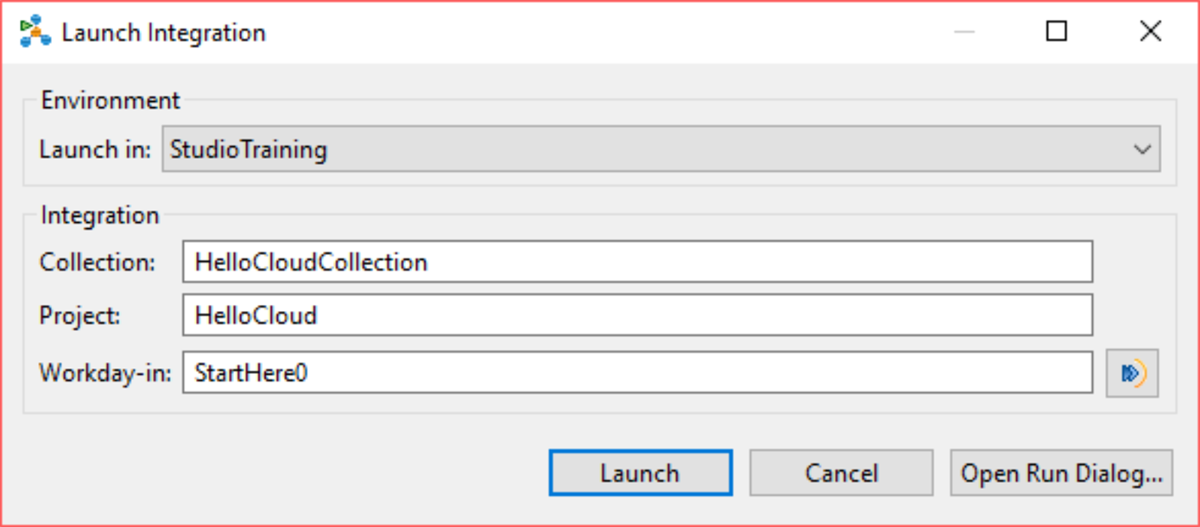
View launch parameters
Process Monitor
Workday Studio contains a process monitor to review the results of the integration event. The process monitor view shows the status of the event, which may be preparing, waiting, processing, or completed. The status should automatically update, but you may right-click the row for the event and select Refresh.

Process Monitor
If you have included a log step in the assembly, it is written to a log file which is viewable in Workday Studio. To view this log, right-click the row for the event and select View Log File or double-click the row for the event.
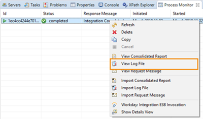
Process monitor log file menu item
Each integration event is viewable in the Workday tenant. You can view the integration event in the tenant by running the
Integration Events
report.You may also right-click the row for the event in the Workday Studio Process Monitor view and select Workday: Integration ESB Invocation to be taken to the event in the tenant.
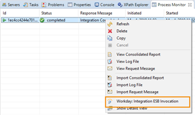
Access event information from the process monitor
The integration event in the tenant presents all the information about the event, including the messages written to the event through the PutIntegrationMessage component. (Note: PutIntegrationMessage messages also show up in the log.)
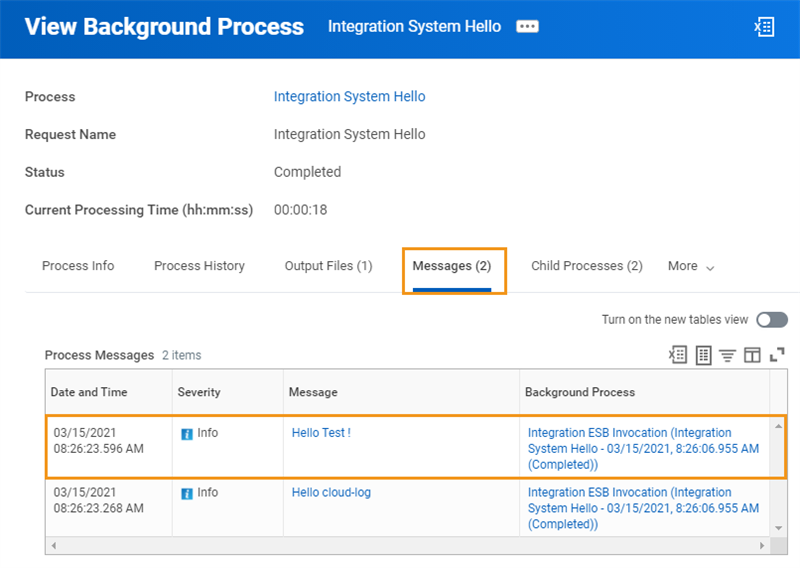
View Background Process
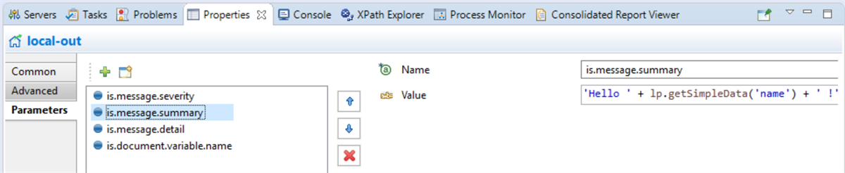
These messages are defined in the Parameters tab in the properties of the PutIntegrationMessage component.
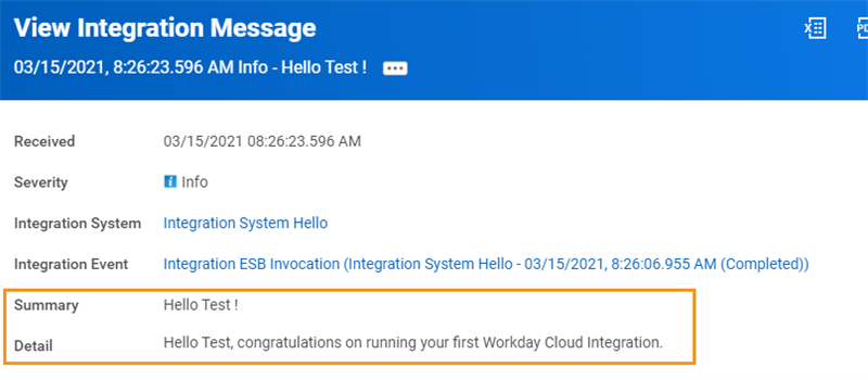
View Integration Message task

Workday Studio message parameters
Launch Integrations from Tenant
Once you deploy the integration system, you can also launch it from the tenant. Navigate to the integration system in the tenant, then use integration system's Related Actions to Launch or Schedule the integration system.
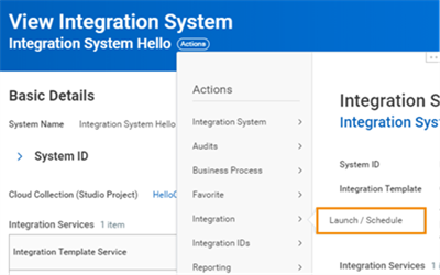
Launch/Schedule integration menu item
Note
: You may see all launches of Workday Studio integrations, regardless of where they were initiated in the tenant's Integration Events
report. This is in contrast to the process monitor in the Workday Studio client that will only report the launches started within the Workday Studio client.Cloud Runtimes
When an integration is launched, Workday allocates a cloud runtime to the integration event. This ensures that integrations are protected from each other. Instead of executing integration events immediately, the Workday network server places them in a queue to await access to an available cloud runtime. When a cloud runtime becomes available, Workday retrieves the integration from the repository and deploys it for execution.
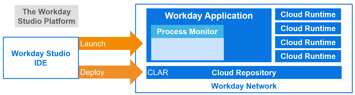
Cloud runtime integration
Processing and File-Size Limits
Design Workday Studio integrations to finish running within two hours. A Workday Studio integration may run for up to four hours in production if resources are available; however, this extra processing time cannot be guaranteed.
Workday terminates any Workday Studio integration that:
- Generates more than 3 GB of files during the integration run.
- Generates any single file larger than 1 GB during the integration run.
- Uses more than 12 GB of memory during processing.
There are a few other limits that you should be aware of:
- XPath operations cannot be processed against XML that contains more than 1 million characters.
- Custom reports are limited to 2 GB.
- An integration's delivery and retrieval services cannot deliver or retrieve more than 5000 integration documents per integration run.
Adding Components to the Assembly
Add components by dragging them from the palette over onto the assembly diagram:
Notice the swimlane component found in the annotation category, which provides a convenient way of organizing components together.
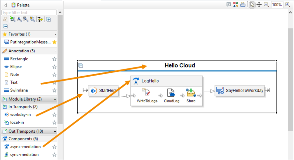
Adding components to the assembly
If a component has parameters, like the PutIntegrationMessage, when you drop it on to the diagram a wizard will display a list of those parameters.
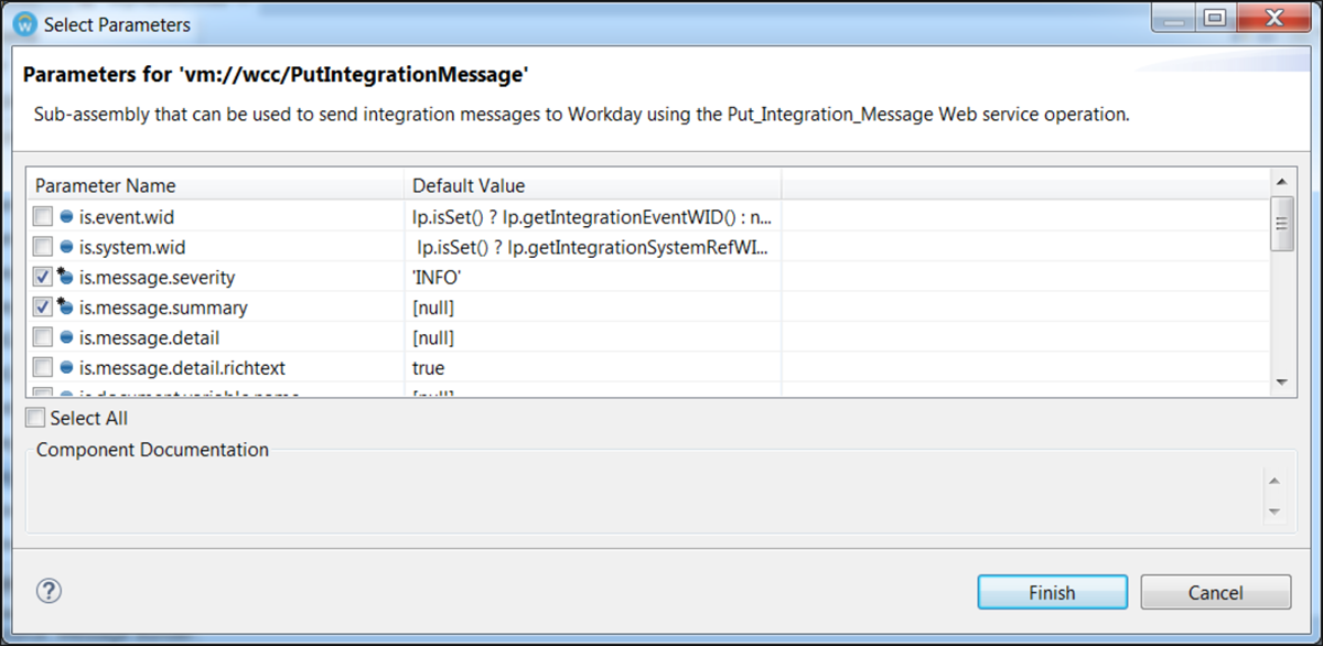
Component parameter wizard
After you add a component to the assembly diagram, you configure it by right-clicking on it, then selecting Show Properties View. The Properties view displays a list of all properties required to configure that component.
You may use the help links displayed at the bottom of the Properties view to find out more about each component and how to configure it.
Finally, the components must be "wired" together to define the message path. You may use either the boxes to drag and drop, or the Routes To property, to wire two components together.
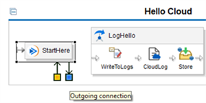
Define a message path
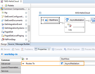
Component properties
Assembly Diagrams
Care should be taken when creating an assembly to arrange the components so that it is easy for another developer to understand how the assembly behaves.
- Use swimlanes to easily organize your components into logical units and manage overall flow.
- Arrange the assembly components so messages flow from left-to-right and top-to-bottom.
- When you are ready to deploy to Production remove any unnecessary log steps. Remember, they are an aide while developing but they can have an adverse performance impact.
- Break up assembly components into logical and functional sub-assemblies (using local-in and local-out transports). This will aid readability of the main assembly flow and permits isolated and logical unit testing.
- Add notes to individual components explaining anything of interest. This is particularly useful on routing steps are components where an "Execute When" condition has been added.
- Do not have arrows that cross each other or other components. Arrows do not have to be straight lines. You can bend them around other components, if necessary, rather than have the lines cross by clicking and dragging on the midpoint.
- Add more HTTP out or Workday out transports if that makes it easier to layout the components. If there are multiple calls to a single web service, it is better to have multiple out transports, than to complicate the assembly diagram by routing all messages to the one transport.
Deploying Workday Studio Projects to Workday
When you select a project to deploy, Workday Studio deploys all other projects that are members of the same collection. To deploy a collection of projects, follow these steps:
- Right-click the top-level project folder in the Project Explorer view, then select Deploy to Workday.
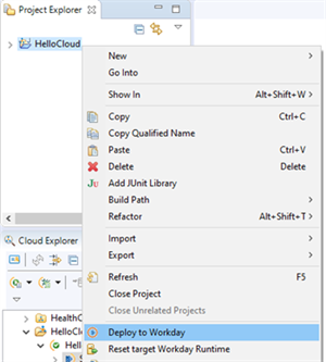 Deploy to Workday menu item
 - The Deploy to Workday wizard opens. By default, the Workday Environments pane shows all Workday environments that you are currently connected to as part of your Workday Studio session. A Workday Environment must be selected in order for the Next and Finish buttons to activate. Additionally a checkbox is presented to include source code in the deployed CLAR. Selecting this option will allow other developers to later import the deployed CLAR directly from the Cloud Explorer. It essentially includes all of the data necessary to rebuild this project in a Workday Studio workspace.
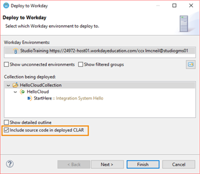 Deploy to Workday environment selection
 - Click Next to continue through the deployment wizard to the Add and Remove screen. This screen has two sections, an Available list on the left and a Configured list on the right. The collections in the Configured list will be deployed upon clicking the Finish button.
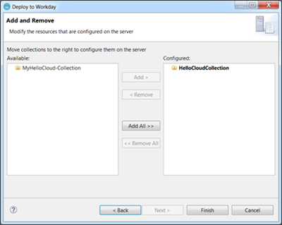 Deployment wizard (The collection associated with the project you initially selected to deploy will automatically appear in bold in the Configured list and cannot be removed. If you previously deployed a collection during the same session, it may also appear in the Configured list, but it will not be bold. If you intend to deploy only the initially selected project and more than one collection appears in the Configured list, click Remove All to clear all other collections. You can also use the Add and Remove buttons to modify the Configured list.)
The Status Bar will display a message once the deploy has successfully completed.

Deployment status message